VIEWSHED ANALYSIS
This exercise uses a combination of vector and raster data for 3D analysis using ArcGIS Pro and ModelBuilder for the computations of visibility models based on lines of sight.
The following variables are used in viewshed analysis:
|
OFFSETA is used to set the observer height above the ground surface, where the observer’s eyes are, for accuracy of visibility in the viewshed analysis. |
|
|
AZIMUTH1 sets the starting angle of the horizontal range of visibility, which is useful for setting a specific direction of interest. |
|
|
AZIMUTH2 sets the ending angle of the horizontal range of visibility. Combined with AZIMUTH1 to specify an area of focus. |
|
|
RADIUS2 is used to define the maximum distance of visibility from the observer point. This creates a boundary for visual analysis. Cells beyond the boundary are excluded from the analysis. |
The “Use earth curvature correction” option in the Viewshed tool is used to correct for the curvature of the earth and for atmospheric refraction, providing a more accurate analysis. There are several applications of Line of Sight models where the impact of the Earth’s curvature or atmospheric refraction should not be ignored, including:
- Aviation: to ensure navigation and communication signals are not obstructed
- Cell towers: for best signal coverage
- Satellite Communications: clear visibility is important for tracking and communications
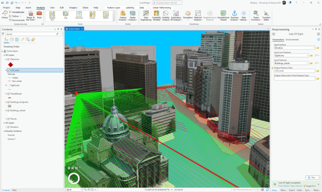
In the following 3D scene, the green lines represent visible areas from the observation point marked with a red diamond. The red lines represent areas which are not visible from that observation point.